Air Forces, Moments and Damping on Model of Fleet Airship Shenandoah (1926)
NASA Technical Reports Server (NTRS) · leaf 7
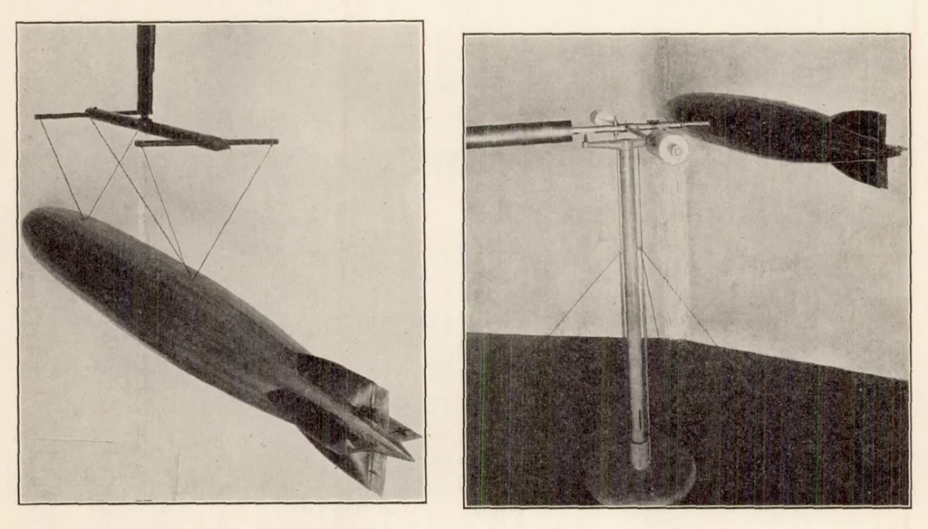
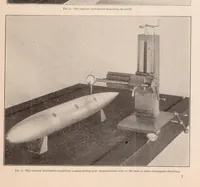
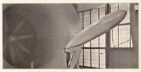
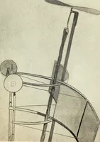
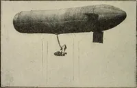
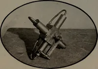
asured simultaneously. The damping coefficients were determined with the aerodynamic oscillator shown in Figure 8. The oscillator axle had a counterweight at one end, and at the other ran squarely into the hull at its buoyancy center. The wind speeds and model settings for the various tests are… … Fig. 1.—Model of fleet airship No. 1 suspended on wind balance Fig. 8 DRAG OF BARE HULLS Tables II and III give the head-on drag and the shape coefficient for the bare hulls, long and short, as found for speeds of 20, 30, 40, 50, and 60 miles an hour; also the head-on drag and shape coefficient for…
NASA Technical Reports Server (NTRS)
Internet Archive · NASA Technical Reports · Public domain (US government work). Free to use for anything.