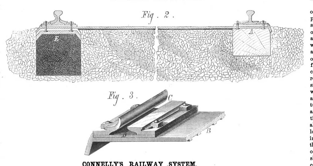
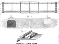
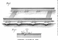
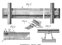
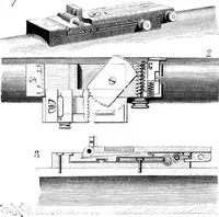
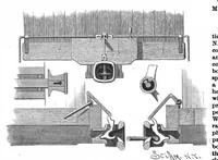
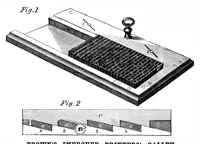
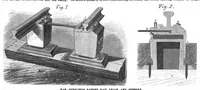
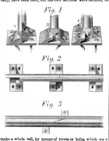
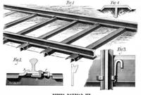
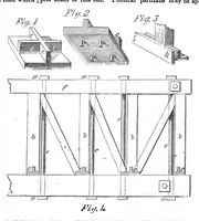
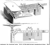
heel in the will first explain the former, groove; the plate is slid forward which is shown at the lower until it touches the heel, and is side of Fig. 1, and, in detail then fixed in that position by cross section, at A, Fig. 2. the screw in its center. Only The sleepers are 10 by 12 . the length… … shell and loading with a new CONNELLY’S RAILWAY SYSTEM. which arrangement is seen in cartridge, are effected. Upon Fig. 1. The wide clamps are T aising it, the extractor is drawn back and the empty shell withdrawn from the barrel; and made sufficiently high to take the place of a fish bar, as ozone…
Internet Archive · Public domain (published before 1931). Free to use for anything.