The Civil engineer and architect's journal, scientific and railway gazette (1839)
London : [William Laxton] · leaf 270
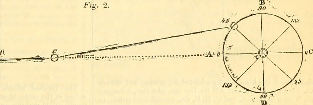
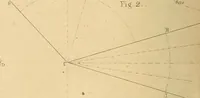
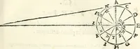
Fig. 2, shows the position of the connecting-rod, as applied from the present horizontal cylinders.(I, II, are guides through hIiIcIi the piston-rod is worked freely; forming its jjarallel motion.b, represents the connecting-rod, when the crank is at an angle of 45 degrees,f, end uf… … No. 1.—From A to B. No. 2.—From B to C. In this Experiment, the V eight No. 3.—From C to D. No. 4.- -From D to A. | In this E.Kperiment, a 10 Ib.s. Weightwas suspended at the end of thethrow ot the Crank, commencing was passed over a Pulley, and at- tached to the throw of the Crank ; III his…
Architecture · Civil engineering · Science
Internet Archive · Boston Library Consortium · Public Domain Mark 1.0. Free to use for anything.