Hobart, H. M. (Henry Metcalf), 1868-1946 ed · Philadelphia, J. B. Lippincott · leaf 103
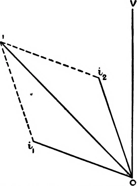
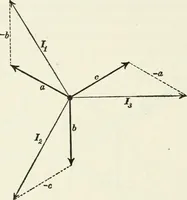
Fig. 1.—Connection of Phase-splitting Device divide into two, one containing high induc-tance, and the other high resistance. In fig. 1 let L and r represent the induc-tance and resistance respectively connected tothe windings of a rotating field device M, suchas a motor. Then if the line o v in… … Fig. 2.—Vector Diagram of Pliase-splitting Device lagging a small amount behind ov, whilst thecurrent in the L circuit will be represented bysome line 08; lagging nearly 90° behind 0 V.I will be the line current which has thus beensplit into two components i^ and i^. [r. c]Phases, Rotation of.—In a…
Electrical engineering
Internet Archive · Cornell University Library · Public Domain Mark 1.0. Free to use for anything.