The design, construction and test of a direct reading engine indicator (1917)
Tower, Alexander McJunkin, Siegmund, Humphreys Oliver · leaf 56
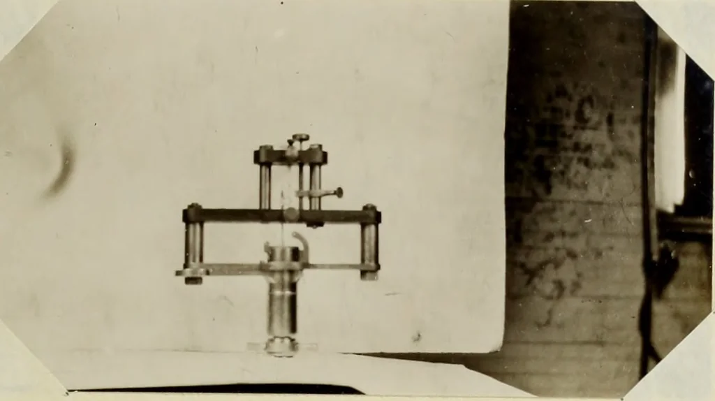
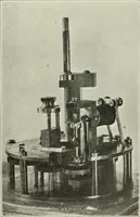
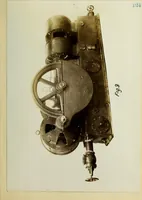
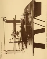
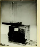
part of the original indicator.The fibre support B holding the bridge wire is held in place by thebrass pillars C and is bolted down as shown. The other fibre bridgewire support D is held in place by smaller brass rods E. The bridgewire W is held in brass lugs that are tightened by set-screws… … Fig. 24. Photograph of Completed Indicator. indicator plunger at K. A copper helix connects the slider to thegalvanometer terminal N. The fixed contact P is adjusted by themicrometer screw Q and is held fast in place by another thumb-screwR. The other galvanometer circuit terminal T is made a part…
Internal combustion engines · Theses
Internet Archive · University of Illinois Urbana-Champaign · Public Domain Mark 1.0. Free to use for anything.
![An illustration from Description abregée des principaux arts et metiers et des instrumens qui leurs sont propres. Le tout détaillée par figures / [Anon]. (1743)](https://img.insideoutlibrary.com/img/200/wellcome-wellcome_b30409482-171-1.webp)