Draw frames and fly frames : being a practical treatise on the above machines (1898)
Thornley, T. (Thomas) · Manchester : A. Heywood · leaf 69
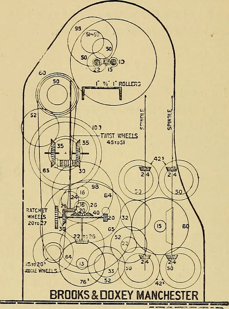
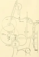
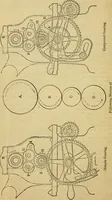
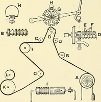
he two rows of spindles are placed on opposite sidesof their respective spindle shafts. See Fig. 20. SWING. The wheel 65 placed next on jack shaft to the 65 spindledriving wheel, and is compounded with the loose bevel wheel35 in the differential motion and is the first wheel in the seriestermed the… … DIAGRAM OF ROVING FRAME GEARING Fig. 20. BOBBIN WHEELS. Exactly as in the case of the spindle driving, there aretwo bobbin shafts extending the whole length of the frame,one being driven from the other, and therefore running inthe opposite direction. There are in the same way 50sbevels on the…
Textile machinery
Internet Archive · UMass Dartmouth, Claire T. Carney Library · Public Domain Mark 1.0. Free to use for anything.