The practical telephone handbook and guide to the telephonic exchange (1906)
Poole, Joseph · New York, Macmillan Co. · leaf 134
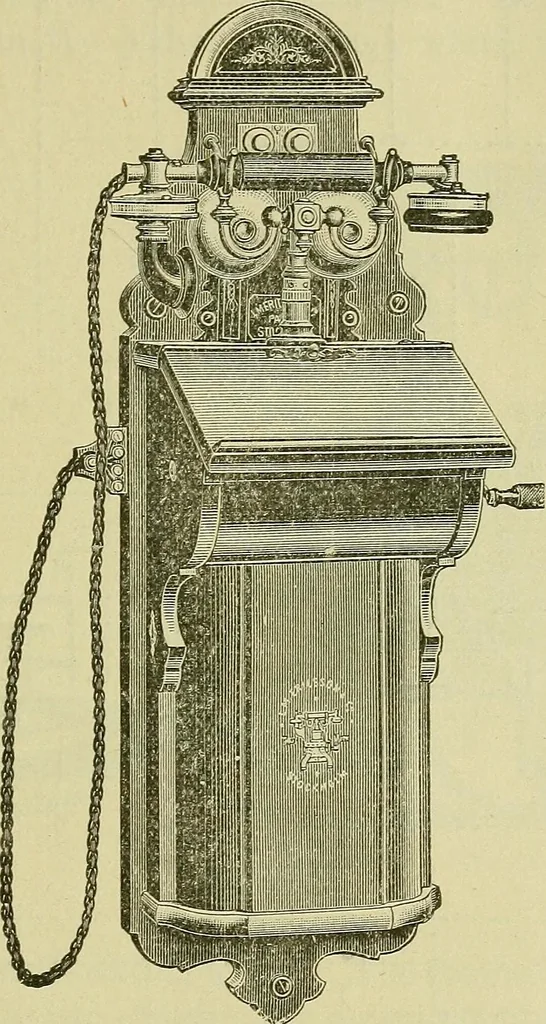
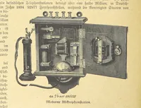
Fig. 114Between the two pairs of terminals at the bottom, marked SUB-STATION INSTRUMENT CONNECTIONS m T t, one or two receivers may be connected ; if the latter theywill be connected in parallel. Between the p pair the primarycircuit of the transmitter is connected—one to one end of theinduction… … Fig. 115 the left, No. 1 Line, Earth, No. 2 Line, and Extension Bellwires Nos. 1 and 2. The two latter terminals are for con-necting an extra bell, to be rung in some other part of thebuilding. It is connected (if required) as a shunt to theinstrument bell, a 2-way switch being often used in…
Telephone
Internet Archive · Northeastern University Library · Public Domain Mark 1.0. Free to use for anything.