The thermionic vacuum tube and its applications (1920)
Van der Bijl, Hendrik Johannes, 1887- · New York McGraw-Hill Book, Co · leaf 236
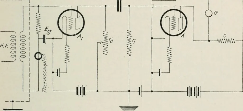
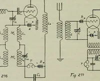
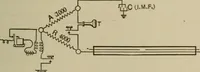
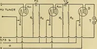
with the circuit arrangement shown in Fig. 109,for which I am indebted to my associate Dr. J. B. Johnson. Aiis the tube with which the high-frequency current was amplified.The a-c. output voltage from this tube was measured by meansof a bridge arrangement shown on the right of the figure, inwhich… … Fig. 109. of the tube A, which acts as a detector, so that small potentialvariations applied to its grid unbalances the bridge. The bridge was calibrated by applying known a-c. voltagesto the grid of tube A, and noting the deflection of the galvanometerG. The known voltage is applied, as is…
Telegraph, Wireless
Internet Archive · Gerstein Library, University of Toronto · Public Domain Mark 1.0. Free to use for anything.