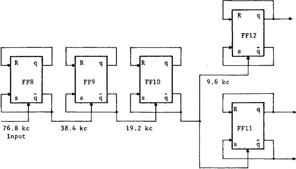
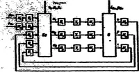
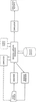
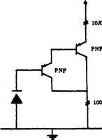
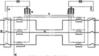
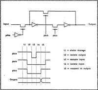
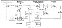
ND- NOR gate (SN514) arranged in a ring counter as shown in figure 50. Since a positive voltage is here employed as a logic each half of the gate is a NOR circuit. If either input 1, 2 or 6 is a logic “1”, then one of the three associated transistors will be turned on and output 8 will be a logic… … 9.6 kc Figure 49. — Frequency countdown circuit. Positive Logic Figure 50, — Block diagram of the pulse sequence generator.
Research triangle inst research triangle park nc · Microelectronics · Space sciences · Electronics · Skills · Structures · Availability · Subminiature electronic equipment · Expansion · Circuits
Internet Archive · Defense Technical Information Center · Public domain (US government work). Free to use for anything.