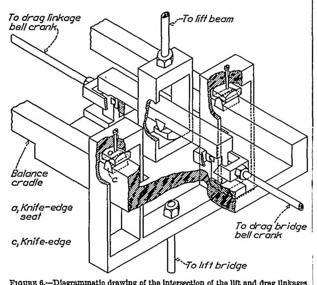
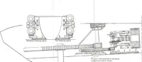
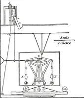
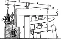
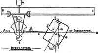
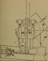
he forces to the balance beams from the cradle to which the model is rigidly fastened. linkages.—Figure 5 is a diagrammatic drawing of the balance showing the main parts. The balance cradle, which is a rigid structure extending across the tunnel under the test section, is suspended by rods from two… … Fioote 6.—Diagrammatic drawing of the Intersection ot the lilt and drag linkages the sides of the cradle are the lower horizontal members, on each side of the test section. The balance cradle would thus be free to move along the tunnel axis if it were not restrained in this movement by the drag…
NASA Technical Reports Server (NTRS)
Internet Archive · NASA Technical Reports · Public domain (US government work). Free to use for anything.