Pomilio, Ottorino · New York, McGraw-Hill · leaf 362
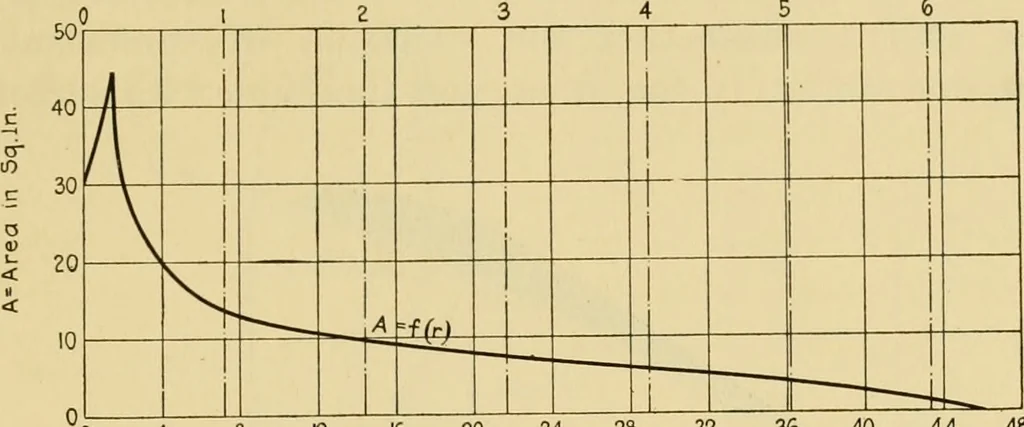
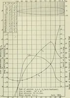
the areas of the various sections A,we shall be able to draw the diagram A = f (r) of Fig. 214,which by means of formula (1) permits drawing the otherone d^ ., . whose integration gives the total centrifugal forces $which stress the various sections (Fig. 215). FUSELAGE, LANDING GEAR AND PROPELLER… … 16 20 24 2& 32 36Radii -in Inches surface element of the blade, and U is the relative velocityof such a blade element with respect to the air. Calling I the variable width of the propeller blade, we maymake dS ^ I X dr
Airplanes
Internet Archive · Public Domain Mark 1.0. Free to use for anything.