Duncan, J. (John), d. 1941 · London, MacMillan and co., limited · leaf 490
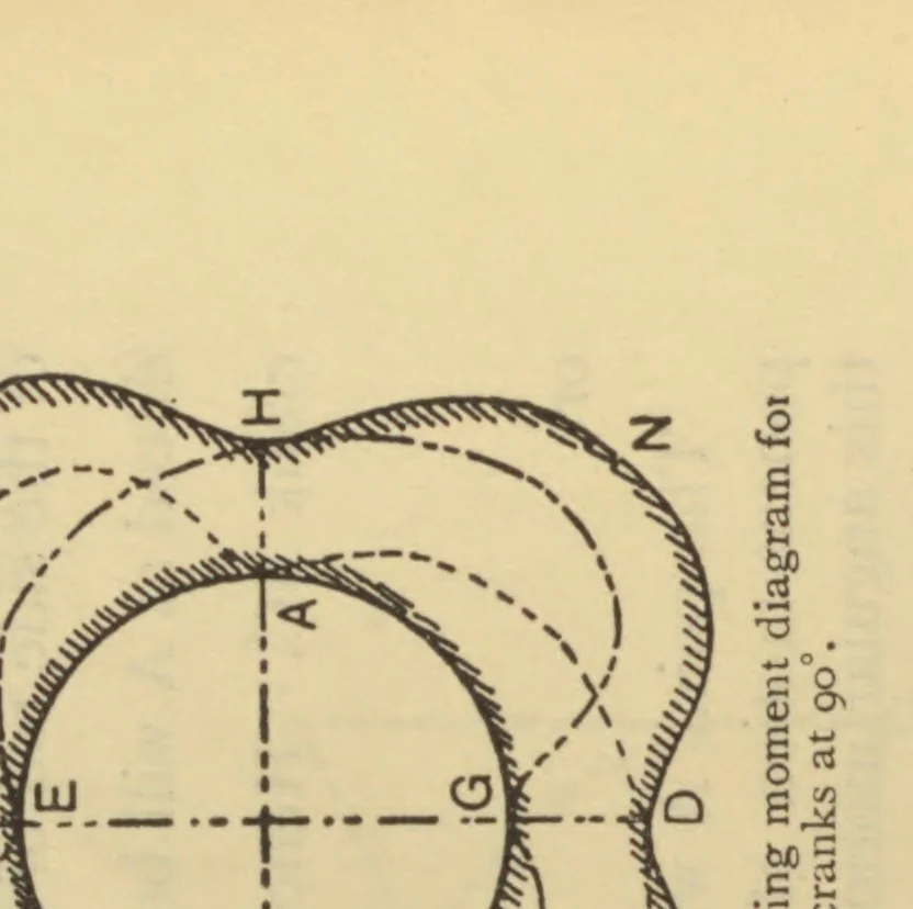
d the turning moment diagramsfor each crank separately are shownby ABCDA and EFGHE; theseare displaced relatively to each otherby 90°. Summing the corresponding ordinates, the combinedturning moment diagram is HKBLFMDNH. Greater uniformityhas been obtained, and there is no point where the turning… … FIG. 512.—Turning moment diagram fottwo cranks at 90°.
Mechanics
Internet Archive · California Digital Library · Public Domain Mark 1.0. Free to use for anything.