Chicago : Engineering and Contracting Pub. Co. · leaf 80
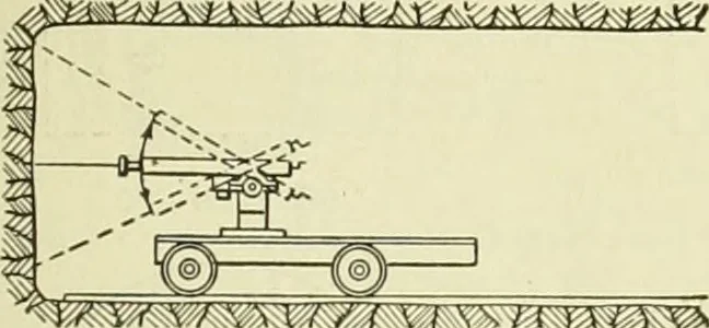
Fig. 2—Drill Shaft in Position to be Jacked. … is 1 r n7~wt / y / \ / v\ i r\ \r\ x*Fig. A—Vertical Range of Drills. ing was driven along the bottom of the tun-nel and shafts were opened up from 25 to 70yds. apart, from which smaller headings weredriven right and left. The tunnel was en-larged to its full section at different…
Buildings
Internet Archive · University of Illinois Urbana-Champaign · Public Domain Mark 1.0. Free to use for anything.