The Civil engineer and architect's journal, scientific and railway gazette (1839)
London : [William Laxton] · leaf 357
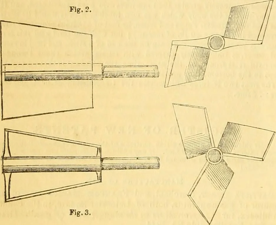
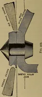
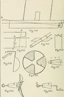
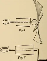
df, and from / draw a perpendicular to the base line c h, then_/e issaid to be the sine and f d the cosine, of the required angle. Thewidth of the floats should not, it is said, in any part exceed the slnefe.Figs. 2 and 3 in the annexed diagrams show two side views of apropeller having the floats… … Fig. 6. of a cone, the apex of which is foremost, or next to the stern of theboat. Fig. 4 shows an end view of the propeller, and shaft in sec-tion. Fig. 5 shows an end view of a similar propeller, but havingthree floats or vanes in place of two. Fig. 6 is a side view of a pro-Fig, c.
Architecture · Civil engineering · Science
Internet Archive · Boston Library Consortium · Public Domain Mark 1.0. Free to use for anything.