The Civil engineer and architect's journal, scientific and railway gazette (1839)
London : [William Laxton] · leaf 202
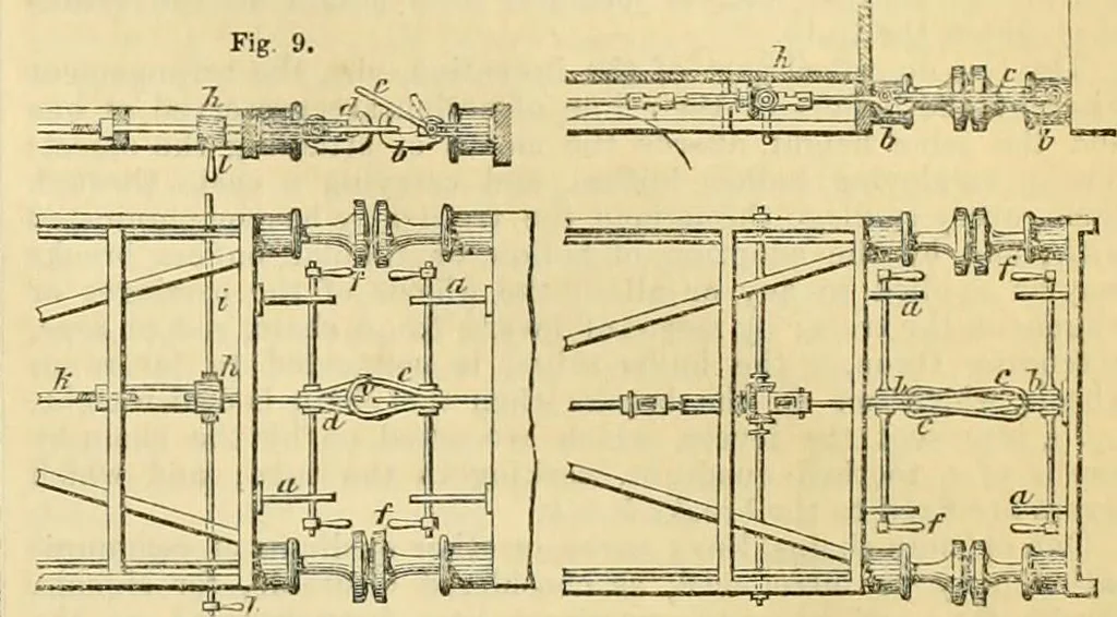
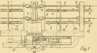
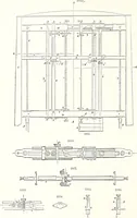
e coupling, a, n,a, are brackets, for supporting the rods which carry the hook-links; b,b, are the hooks; c, c, the coupling-links, placed in theircoupled position. At e, (see fig. 6,) the right-hand link is shownas turned up uncoupled. J\ J\ are handles for working thecoupling-links: they may be… … Fig. 8. Fig. 7. Figs. 8, and 9, show, in plan and side views, a modification ofthe above-described arrangements. «,«, are the brackets; 6,6,the hooks; and r, and rf, the links. The right-hand link d, isshown as coupled; and the left-hand link c, falling down over thelink rf, to be coupled. /, are…
Architecture · Civil engineering · Science
Internet Archive · Boston Library Consortium · Public Domain Mark 1.0. Free to use for anything.