A course on the stresses in bridge and roof trusses, arched ribs and suspension bridges (1904)
Burr, William H. (William Hubert), 1861-1934 · New York : Wiley · leaf 168
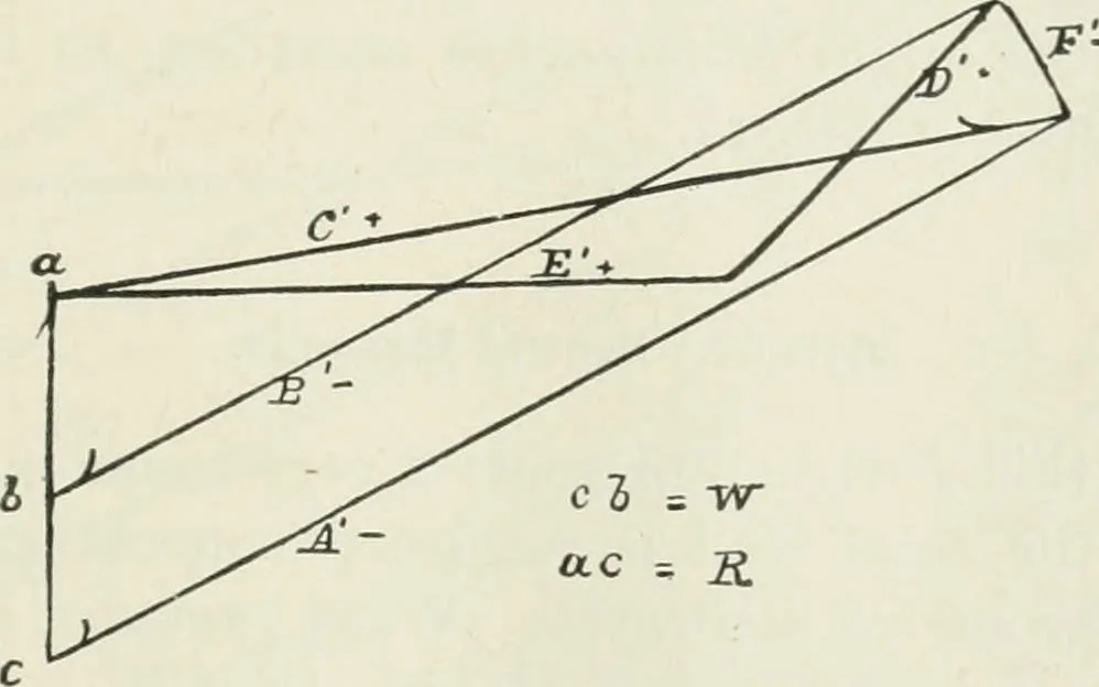
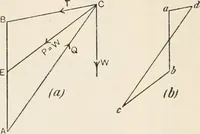
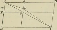
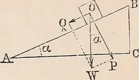
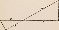
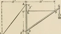
Fig. I. There is no essential error in this case in assuming all theload concentrated at the points indicated. The wind press-ure is assumed to act on the left side of the truss, so thatW>W^> W^. Also, JFi = 1 (JF+ W^). A and B are equalin length, and E is horizontal. Figs. 2 and 3 are the… … Fig. 2. Fig. I. The kinds of stresses in the different members areshown by the signs + or —, in both figures, signifying tensionor compression, respectively. Il8 NOA-CONTINUOUS TRUSSES IN GENERAL. Fig. 2 is the diagram for the vertical loads, and Fig. 3 thatfor the horizontal loads/. {^ c^__^ -7^ ^…
Trusses · Bridges
Internet Archive · California Digital Library · Public Domain Mark 1.0. Free to use for anything.