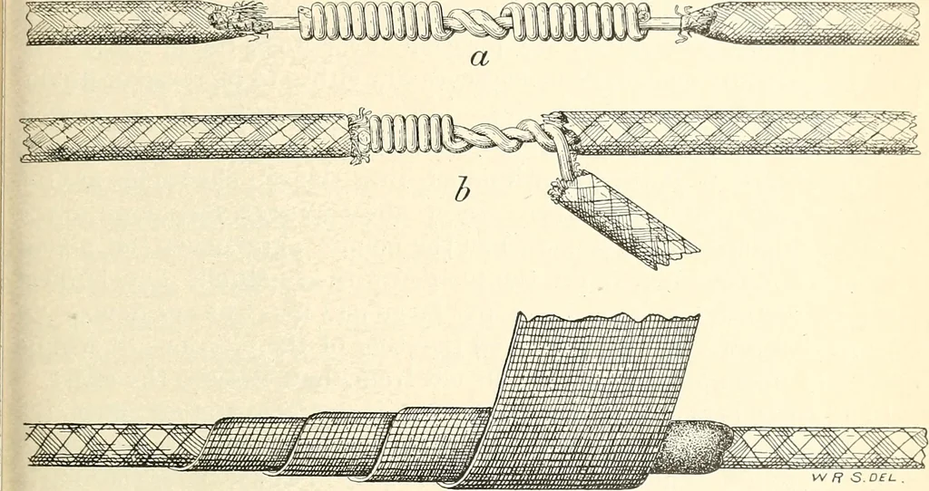
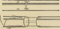
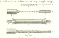
d twisted together at a point aboulthree-fourths of an inch from where the insulation begins. This formsthe middle part of the splice. Grasping this firmly in a pair of pliers,the free end of each wire is wrapped tightly around the straight por-tion of the other, as shown. This splice should be… … Fig. 8.—Splicing and insulating wires: (a) Telegraph splice; (b) Side connection; (c) Taping the splice. making connection between the temperature cell and the soil electrode,is illustrated in fig. 8, />. The insulation is removed for a distance of 1.]inches from the wire to which the splice is…
Soils Analysis · Electric apparatus and appliances
Internet Archive · Public Domain Mark 1.0. Free to use for anything.
![An illustration from [Electric engineering.] (1902)](https://img.insideoutlibrary.com/img/200/ia-electricengineer03inte-456-283.webp)