The illustrated architectural, engineering, & mechanical drawing-book : for the use of schools, students, and artisans ; upwards of 300 illustrations (1856)
Burn, Robert Scott · London : Ward and Lock, 158 Fleet Street · leaf 128
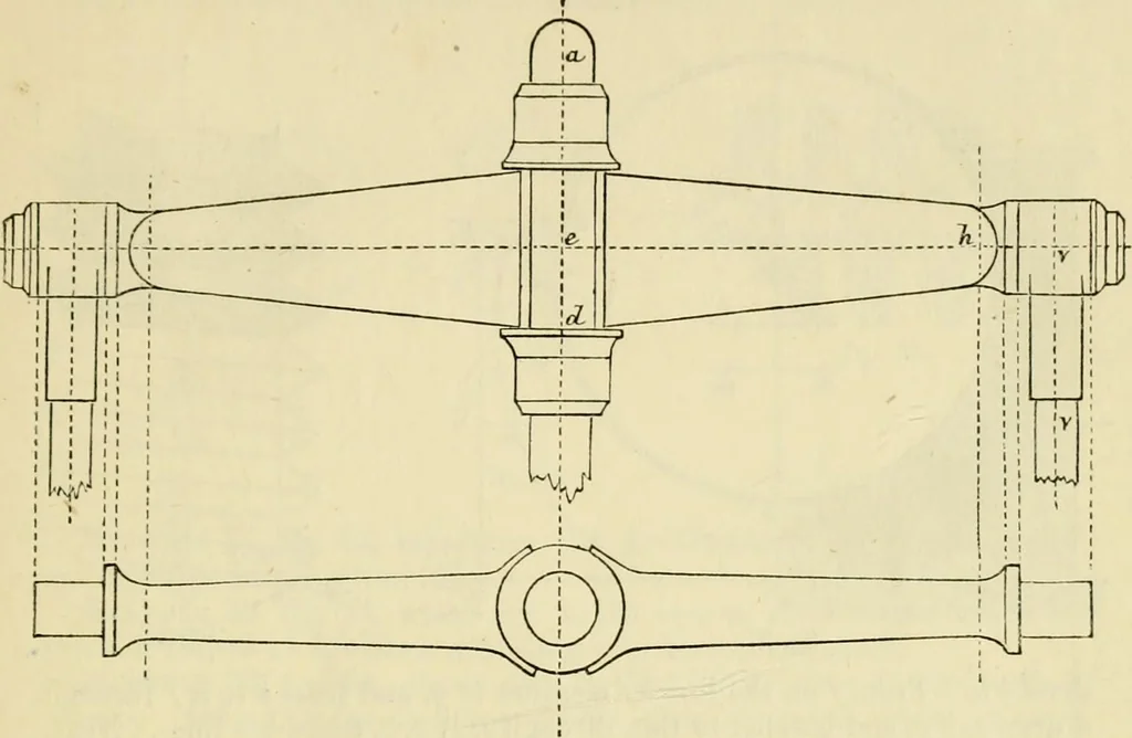
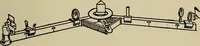
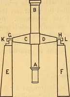
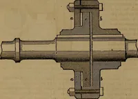
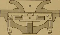
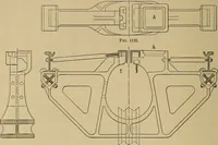
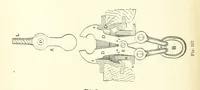
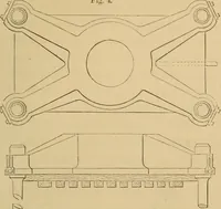
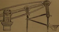
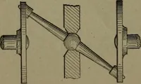
fig. 24 r.XGIXEEniNO, AND MECHANICAL DUAWING-COOK. 125 Example 24, iig, 25, represents the front elevation of a cross headand side levers. The centre-lines are a <f, e h, v v. The plan is shown … fig. 25. below, the lines of which are obtained by continuing those of the upper figure, as in the drawing. Example 25, fig. 26, representsthe front elevation of the cover fora gas retort. The centre of theparts b, c, and d is at a on the lined e ; the centre of the curve joining-op at w, on the…
Architectural drawing · Mechanical drawing
Internet Archive · Public Domain Mark 1.0. Free to use for anything.