The investigation of a reinforced concrete deck girder highway bridge (1914)
Warren, Frank Baker · leaf 32
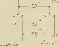
in order to take the greater part of theload off of the old abutment. These columns can be seen in thepicture of the bridge,on the face of the abutment. 12 III. COMMUTATION OF STRESSES. A. Table of Weights. Par t r > ■ ■ 1 - ! > Wt.^er linear ft.-lb. Ut. Persq.. ft.-lb. Total ..t. forone… … ^ - 3 4- - / 3 - & u f e. 13 Section over outer edge of girder. (See Fig. I D.L.M. = -41 x 355 - 97 x 4.08 X ^ - 50 x 3 x IB = - 26,950 lb. in.L.l.lt. = - 915 x 3 x 16 - 49,400 lb. in.Total Ma- 76,350 lb. in. d = 5 1/2 in. .60 P *0 = - .0091 5.5 x 12 *y 2pn (pn)^ - r.n T/2 x .0091 x H \ .0091 x…
Bridges · Reinforced concrete · Girders · Theses
Internet Archive · University of Illinois Urbana-Champaign · Public Domain Mark 1.0. Free to use for anything.