Journal of the Association of Engineering Societies (1881)
Association of Engineering Societies (U.S.) · New York, [etc.] Board of Managers · leaf 102
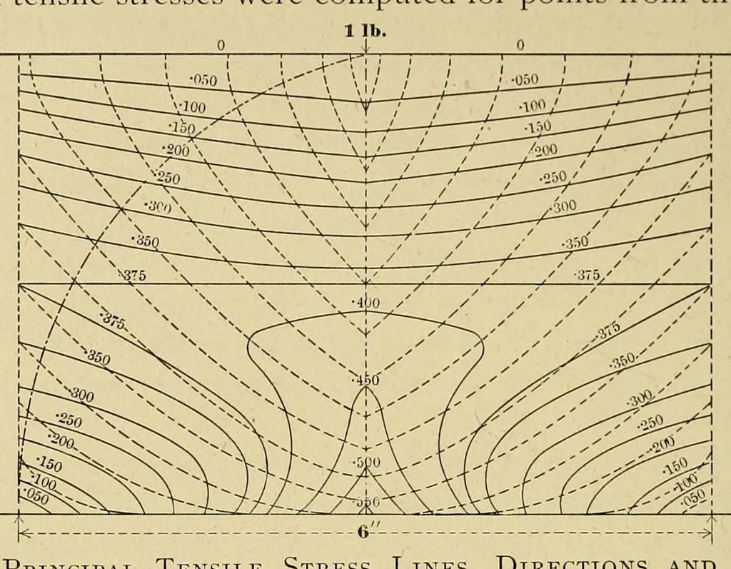
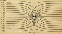
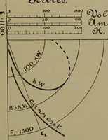
ASSOCIATION OF ENGINEERING SOCIETIES. Figure 7 represents a brick 8" long, 4" deep and i" wide, on supports 6" apart and loaded with one pound in the middle. The principal tensile stresses were computed for points from the center … Fig. 7. — Principal Tensile Stress Lines, Directions and Line of Rupture. to one support (the two halves being symmetrical) varying from each other by distances of ^" vertically and horizontally. Lines were then drawn, connecting points of equal stress*, which are *The general formula for the…
Engineering
Internet Archive · Smithsonian Libraries · Public domain (published before 1931). Free to use for anything.