Naval architecture: a manual on laying-off iron, steel, and composite vessels (1898)
Watson, Thomas Henry · London; New York: Longmans, Green and co., [etc.] · leaf 319
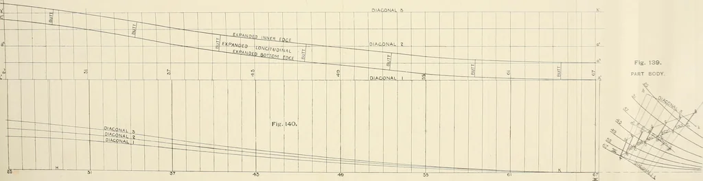
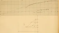
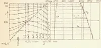
, b, c will be below, and d, e,f,g above <r ;f. Then the lines as g* and A1 G1, Fig. 141, show theexpansion of the surface of the longitudinal A G g a. All the frames and butts are now shown across, and the platesordered. The method comes very near to accuracy, if carefullycarried out. Only the… … DOUBLE BOTTOMS. 135 Expansion by the Mocking=up System.—Fig. 142 showspart of the Body plan on the loft floor with longitudinal sight edgeand the intersection form at various stations. Drop perpendicularsfrom the points A, B, C, D, etc., and from a, b, c, d, etc., on to aconvenient level line L M.…
Naval architecture -- Handbooks, manuals, etc · Naval architecture · Ships, Iron and steel
Internet Archive · California Digital Library · Public Domain Mark 1.0. Free to use for anything.