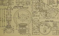
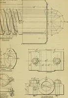
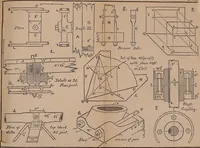
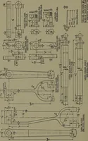
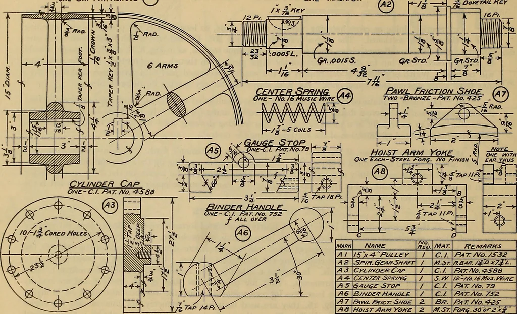
making measurements. They are called center lines in the drawing and are usuallyshown as dash and dot lines. They are base lines for measurements which the workman also must use in layingout his work. In the Bevel Geare, Fig. 16, they are used to indicate symmetr\, for dimensioning the anglesand… … (—2 - Mark NAME No. Mat. Re/^AffHS Al IS~x 4 Po^L£y 1 C.I. P/t-rA/o./SJZ AZ Sffi. G^/)^Shaft / M-5T. /f.BAfi. /^O. X7ii-. A3 Cr/./^o£/fCV / CJ. PytrA/o. 9-saa A4- C£^rr/? v5/°/F/v<7 / s.yy. JZ -A/o. /SAfvS. yy//f£ AS ^-^u^e Stop / c./. Pax A/o. 79 A6 B//^D£^ H/)/^OL E / c./. P/iTA/o. 7S2 A7…
Mechanical drawing · Lettering
Internet Archive · Library of Congress · Public Domain Mark 1.0. Free to use for anything.
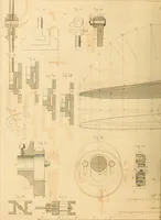
![An illustration from Essai de physique, par Mr. Pierre van Musschenbroek ... avec une description de nouvelles sortes de machines pneumatiques, et un recueil d'expériences par Mr. J. v[an] M[usschenbroek] Traduit du hollandois par Mr. Pierre Massuet .. (1751)](https://img.insideoutlibrary.com/img/200/ia-essaidephysiquep01muss-206-49.webp)