Rogers' drawing and design; an educational treatise relating to linear drawing; machine design; working drawings; transmission methods; steam, electrical and metal working machines and parts; lathes; boiler and parts; instruments and their use; tables, etc (1913)
Hawkins, N. (Nehemiah), 1833- · New York, T. Audel · leaf 216
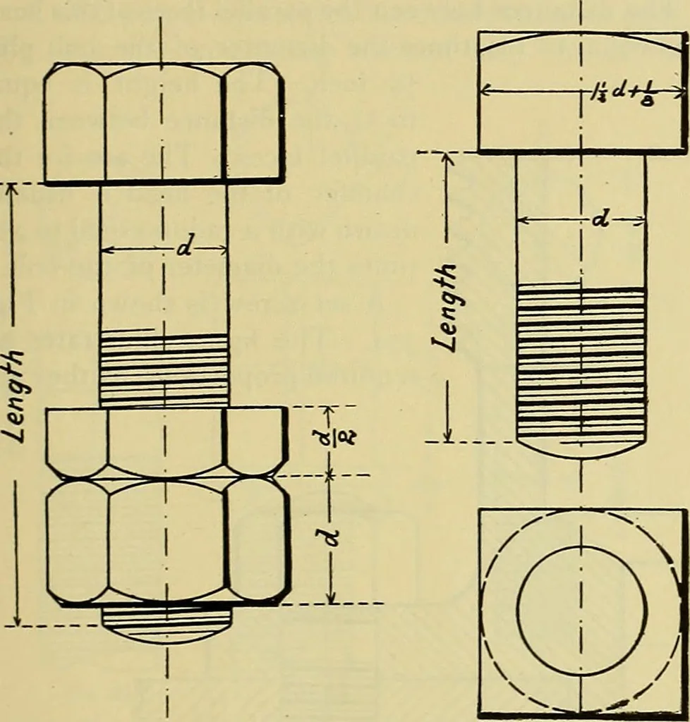
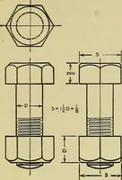
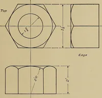
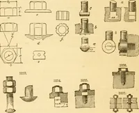
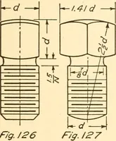
Fig. 351. ROGERS DRAWING AND DESIGN. 239 through these points and extended in both direc-tions so as to cut all vertical edges of the nut in bothviews, at the points a, g, h, k and m. Arcs are then … Fig. 352. Fig. 353. drawn through the points a, b, c and through e, f, g.The same is done in the other view in passing arcsthrough h, i, k and k, 1 and m. These arcs are struck with compasses, after a centre is found by trial withthe compasses. The chamfer at aa and g3 may bedrawn by 45° lines,…
Mechanical drawing · Machine design
Internet Archive · Library of Congress · Public Domain Mark 1.0. Free to use for anything.