Ripper, William, 1853-1937 · London, New York [etc.] : Longmans, Green and co. · leaf 350
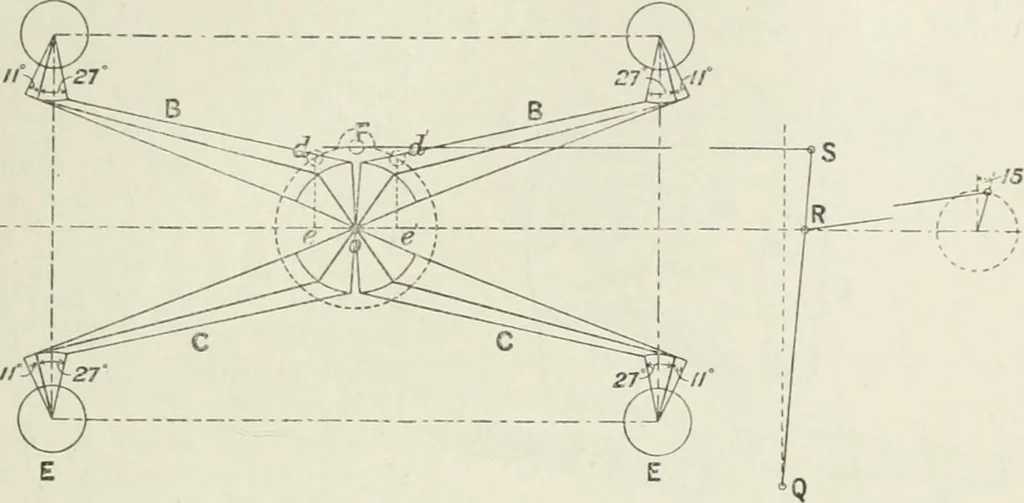
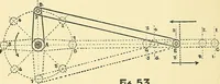
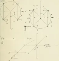
Fig. 384 shows in skeleton the arrangement of levers by which thevalves are driven. Motion is obtained in the first place from aneccentric on the crank-shaft which is connected by its rod to avertical rocker-arm, QRS. Attached to the rocker-arm is the hookrod or lever FS which drives the… … Fig. 384. attached to the two upper or steam-admissionvalves AA, and two marked CC, to the twolower or exhaust valves EE. The valve rodsand levers are shown in three positions—inthe middle, and at the two ends of theirstroke. The exhaust - valve rods are connecteddirectly to the exhaust-valve…
Steam-engines
Internet Archive · California Digital Library · Public Domain Mark 1.0. Free to use for anything.