The theory and practice of modern framed structures : designed for the use of schools, and for engineers in professional practice (1897)
Johnson, J. B. (John Butler), 1850-1902, Bryan, C. W. (Charles Walter), 1863-1927, Turneaure, Frederick Eugene, 1886- · New York : J. Wiley & Sons · leaf 253
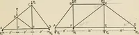
Fig. 260. Fig. 261. first system is shown in Fig. 261, and the second in Fig. 262. The members AB and GD arecommon to both systems. The lengths of the members are given on the left half, and the values of u for I lb. placedat D are given for all the members on the right half of Figs. 261 and 262. … Fig. 262. Fig. 262a. The load at D will divide itself between the systems shown in Figs. 261 and 262; theload at E between the systems 261 and 262^, and similarly with the load at C, provided CGand GE can take both tensile and compressive stress. By Prop. Ill the load at will be divided between the…