Wiring diagrams of electrical apparatus and installations (1913)
McGraw-Hill · New York, McGraw-Hill Book Company · leaf 109
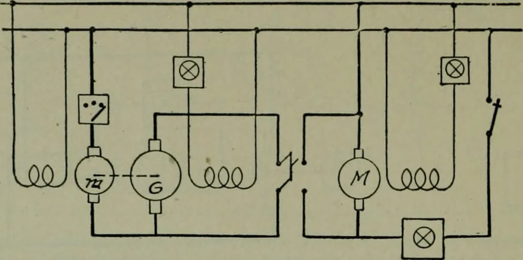
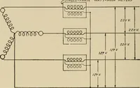
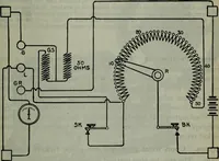
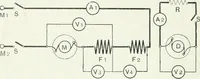
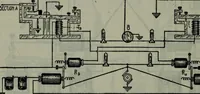
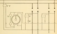
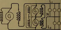
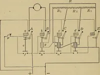
Fig. 155.—Ward Leonard boost and retard speed control sy.stem. The voltage of thegenerator, G, is either added to or subtracted from that of the line by adjusting the field.Speed controlled by adjusting field strength of G. Only part of the power is supplied frommotor m. To obtain speeds below… … Fig. 156.—Teaser system of speed control (Bullock). The generator of the motor-generatorset is wound for low voltage and large current so that in starting it can supply full load currentat such a low voltage that no starting rheostat is needed, and the desired torque can be developedsince it…
Electric wiring
Internet Archive · Public Domain Mark 1.0. Free to use for anything.