American telegraphy and encyclopedia of the telegraph; systems, apparatus, operation (1909)
Maver, William, jr. [from old catalog] · New York, Maver publishing company · leaf 173
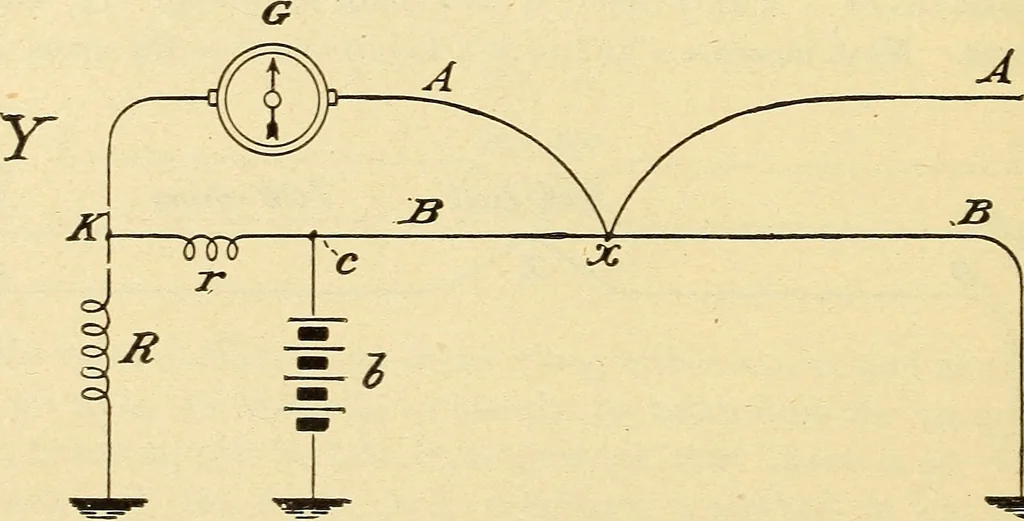
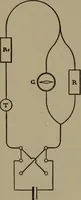
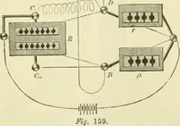
is thus seen that the actual resistance, per mile, of the wire b is not required tobe known. The formula for this test would be A + L F X = 2 where x is distance of fault in ohms, a the result of ist test, l the result of 2nd test,and F the result of 3rd test. LOCATING A CROSS HAVING KESISTANCE—A… … ^ z as before, the test being made from station y. a and b are the crossed wires.G is a galvanometer, one terminal of which is attached to line wire a atstation y ; the other terminal to point k, also in station y. r is a known, moder-ately low resistance, inserted between the line wire b at r, and…
Telegraph
Internet Archive · Library of Congress · Public Domain Mark 1.0. Free to use for anything.