The Civil engineer and architect's journal, scientific and railway gazette (1839)
London : [William Laxton] · leaf 67
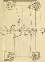
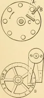
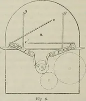
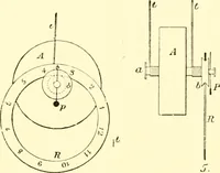
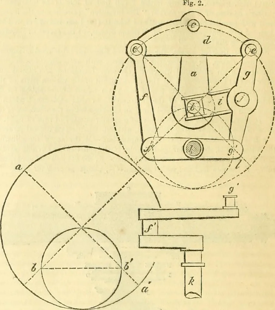
ner. Let a. b, fig. 1 represent the pitch-line of two wlieeis. the wheel abeing twice the diameter of the wheel b; then for every revolution of theM-hee! a the wheel b will make two revolutions, and if a tracing point be at-tached at // it will describe the straight line a a upon the face of the… … Fig. 1. Fig. 3. In fig. 2 is sliown an elevation of the arrangement of levers for connectingtwo shafts together so that they may revolve at different velocities. Fig. 3 isa plan of one of the shafts which is provided with a crank forming a portionof the apparatus. In fig. 2 a is a crank, fixed upon…
Architecture · Civil engineering · Science
Internet Archive · Boston Library Consortium · Public Domain Mark 1.0. Free to use for anything.
![An illustration from [Graphophone patents] (1878)](https://img.insideoutlibrary.com/img/200/ia-graphophonepaten20unit-305-124.webp)