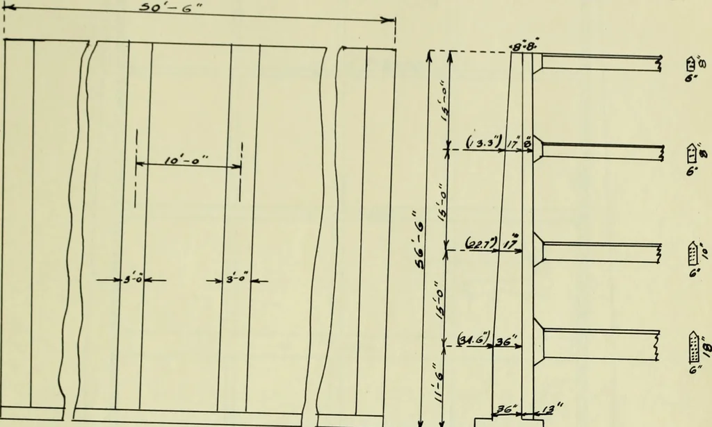
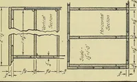
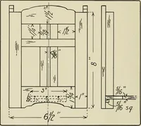
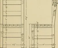
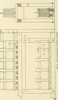
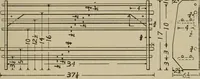
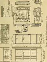
n Pig. 29 in parentheses. The walls as designed, Fig. 29,gives an excess thickness at some points, but was made so toavoid difficult form building and giving an unsightly appearance.The maximum shear in the buttresses occurs at the lower tie rod3and is 113 000 pounds. This will give a stress of 113… … l ... r n Fig £3- Rc+otntng Walt. r-*•-<>—> shown in Fig. 29. The required thicknesses at various points is shown in parentheses at the points for which they werefigured. The required area of tie rods for the various pointsare: \ 6 140/16 000r0.38 sq. in. Use 4-1 bars.R2 56 660/16 000 =…
Bridges · Viaducts · Theses
Internet Archive · University of Illinois Urbana-Champaign · Public Domain Mark 1.0. Free to use for anything.