Mechanical laboratory methods; the testing of instruments and machines in the mechanical engineering laboratory and in practice (1922)
Smallwood, Julian Chase · New York, D. Van Nostrand company · leaf 111
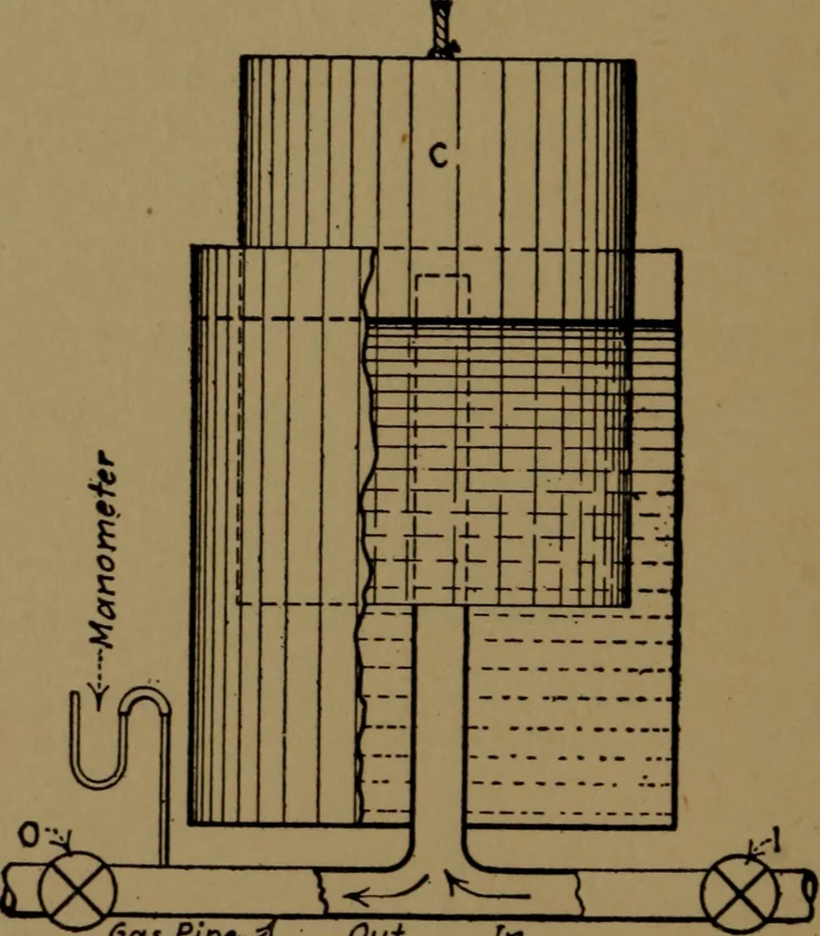
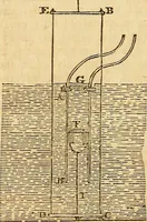
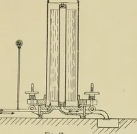
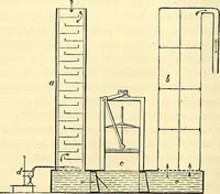
epresented by Fig. 55, and consists of twotanks as shown, the upper one being movable vertically andproperly counterbalanced. This arrangement makes a chamberof variable size and water sealed. When the upper tank is raised.gas is drawn through the inlet pipe, the valve O being closed and /open.… … Gas Pipe-*Out In Fig. 55.—Gasometer. It will be noted that the gasometer cannot be used for measur-ing continuous flow unless two are operated, one to fill and oneto discharge, alternately. Another form of gasometer is shown by Fig. £6. Gas is drawninto the cylindrical chamber C by allowing water…
Mechanical engineering
Internet Archive · Library of Congress · Public Domain Mark 1.0. Free to use for anything.