Harmsworth, Alfred Charles William, Sir, bart · London Bombay : Longmans, Green, and Co. · leaf 143
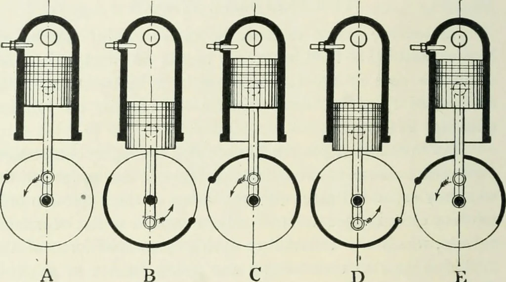
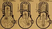
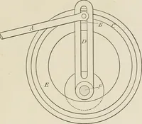
E This is the whole operation :— Fig. 4, Diagram A.—A spot is shown upon the fly-wheelbefore the beginning of the operation. Fig. 4, Diagram B, shows that during the suction strokethe fly-wheel has made half a revolution. Fig. 4, Diagram C, shows that during the compressionstroke a further… … D B C Fig. 4.—A complete Cycle.Suction. Compression. E.xplosion. Exhaust. Fig. 4, Diagram E, shows that during the exhaust strokea fourth half-revolution is made. So for every explosion thereare two complete revolutions of the fly-wheel. INDUCTION VALVES In Fig. 2 it will be seen that the interior…
Automobiles
Internet Archive · UBC Library · Public Domain Mark 1.0. Free to use for anything.