Naval architecture: a manual on laying-off iron, steel, and composite vessels (1898)
Watson, Thomas Henry · London; New York: Longmans, Green and co., [etc.] · leaf 255
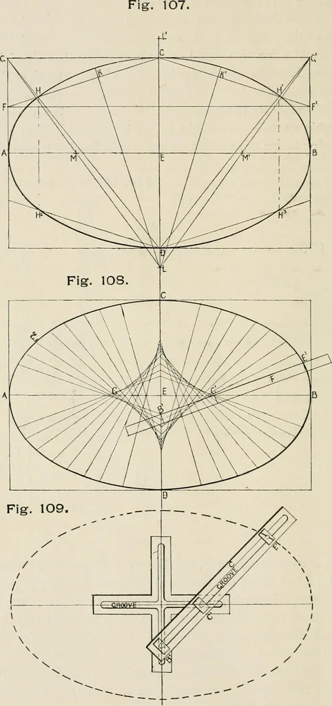
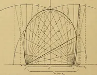
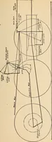
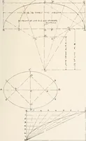
t above the load-line. It is not necessary to place anyfigures, except in shallow draught boats, below about 4 feet, as theship is never likely to draw less water. The after end may be linedoff in the same manner by producing C B A to E and placing straightedge to points E A. Measure up F from A E… … MISCELLANEOUS. 113 To Form an Oval Manhole.—In Fig. 107, let A B be the longest dimension. Bisect it in E, and erect perpendicular ofindefinite length each side of A B. Set off E C and E D each equalto half the shortest dimension. Draw A G and B CI1 parallel andequal to E 0. Bisect A G in F and B…
Naval architecture -- Handbooks, manuals, etc · Naval architecture · Ships, Iron and steel
Internet Archive · California Digital Library · Public Domain Mark 1.0. Free to use for anything.