Naval architecture: a manual on laying-off iron, steel, and composite vessels (1898)
Watson, Thomas Henry · London; New York: Longmans, Green and co., [etc.] · leaf 317
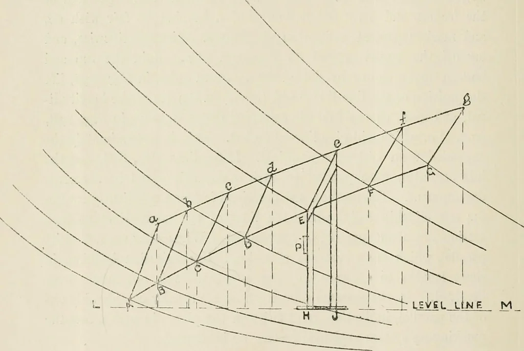
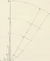
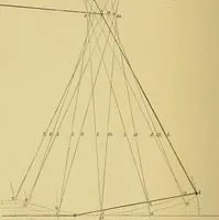
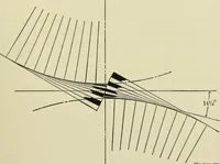
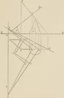
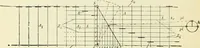
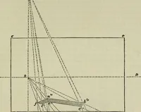
or theframe stations, and lay them out on their corresponding lines fromNo. 07 in the expansion Fig. 141—No. 1 diagonal on A1 L1, No. 2 ona2 g2, No. 3 on hl l;\ Draw vertical curves through the spots, whichwill give form of the frames. Upon these indicate the position ofthe sight edge A G, relative… … LEVEL lIaII above ci~ if on corresponding frames 37, 31, 25. A curve through thespots will give longitudinal sight edge A1 G1. In the same mannerlay off a g relative to a //. The points a, b, c will be below, and d, e,f,g above <r ;f. Then the lines as g* and A1 G1, Fig. 141, show theexpansion…
Naval architecture -- Handbooks, manuals, etc · Naval architecture · Ships, Iron and steel
Internet Archive · California Digital Library · Public Domain Mark 1.0. Free to use for anything.