Naval architecture: a manual on laying-off iron, steel, and composite vessels (1898)
Watson, Thomas Henry · London; New York: Longmans, Green and co., [etc.] · leaf 45
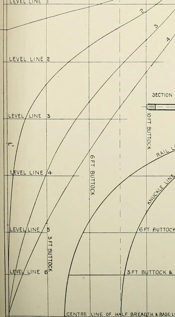
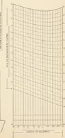
to A B. Liftthe cutting point distances of the several lines a1, b\ and c squarefrom the centre in the Half Breadth, and lay them out on theircorresponding lines in the Sheer, a1 on a a2, b1 on 5 b2, and so on,which will give spots for the section A B. Those for the buttocksmay be got by placing… … Fig. 9. SHEER CENTRE LINE OF H4LF BREADtTH 8. BASE. LINE OF 3«fER 1300 10FT BUTTOCK 6FT PUTTOCK i. LEVEL LINE 5 FT BUTTOCK i. LEVEL, LINE 6 KNUCKLE LINF RAIL LINE WSIDE STRAKF LEVEL LINE I
Naval architecture -- Handbooks, manuals, etc · Naval architecture · Ships, Iron and steel
Internet Archive · California Digital Library · Public Domain Mark 1.0. Free to use for anything.