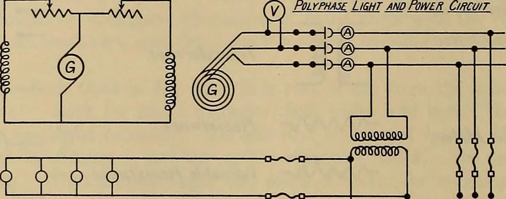
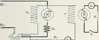
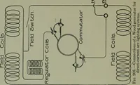
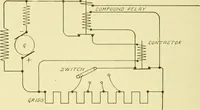
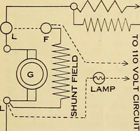
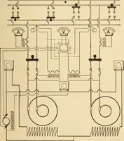
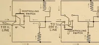
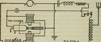
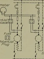
ns where they are omitted.After completing the sketch of projections, put on all the dimensions and specifications needed by the workman. 1.—Center Rest Jaw, Fig. 41. 2.—Flange G, Fig. 42. 3.—^Washer N, Fig. 42. 4.—Box Cap R, Fig.42. 5.—Tailstock U, Fig. 42, 6.—Drill Stop, Fig. 46. 7.—Solid… … <rTT^ k I W Fig. 33. ELECTRICAL SYMBOLS FIG. 32 209. To facilitate the rapid sketching of plans for wiring, some system of symbols for the parts occurringmost frequently is often useful. The ones given here in Fig. 32 have been adopted by the Electrical Engineer-ing department of the Worcester…
Mechanical drawing · Lettering
Internet Archive · Library of Congress · Public Domain Mark 1.0. Free to use for anything.