Creighton, William Henry Paul, 1859- · New York, J. Wiley & sons; [etc., etc.] · leaf 320
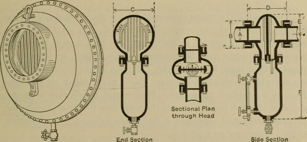
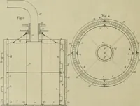
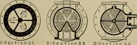
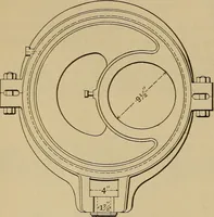
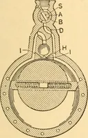
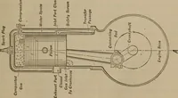
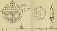
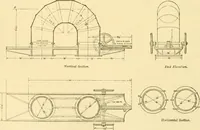
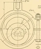
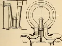
. 299 Fig. 5 represents a separator depending upon centrifugalforce. Figs. 157 and 157a represent separators in which a ribbedbaffle plate is placed at right angles to the current of steam.The ribbing prevents the oil or water from being brushed off bythe deflected steam current. The water drains… … Side Section Fig. 157.—Vacuum Oil Sep-arator for Horizontal Pipes18 inches and larger. Fig. 157a.—Separator. creeps along the interior surface of the exhaust pipe in the direc-tion of the steam current. If oil is to be removed from exhaust steam it should bedone before condensing the steam. It is…
Steam-engines · Heat-engines
Internet Archive · Library of Congress · Public Domain Mark 1.0. Free to use for anything.