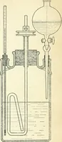
Steam engines, prepared in the Extension division of the University of Wisconsin (1919)
Shealy, Edward Marvin · New York, McGraw-Hill · leaf 280
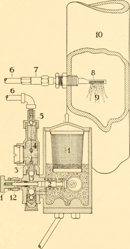
mber of pointsof application demanded in each case. In Fig. 163 the oil reservoir is shown at 1, the level of the oilbeing indicated by a glass gage which is not shown in the illus-tration. The oil reservoir is provided with a strainer so that freshoil poured into it will be strained and any small… … il i2 Fig. 163. stroke. The oil drops form around a guide wire 4 and rise throughwater in the sight feed. They then pass a nonreturn valve 5, andare forced through the check valve 7, at the extreme end of the oilpipe 6, into the atomizer 8, located in the steam pipe 10. By means of the adjusting…
Steam-engines
Internet Archive · Library of Congress · Public Domain Mark 1.0. Free to use for anything.