Twentieth century hand-book for steam engineers and electricians with questions and answers; a practical non-technical treatise .. (1913)
Swingle, Calvin Franklin, 1846- [from old catalog] · Chicago, F. J. Drake & company · leaf 392
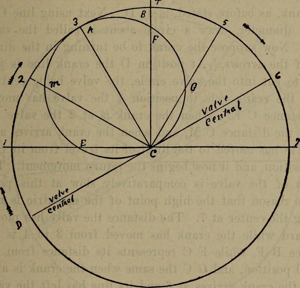
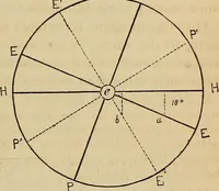
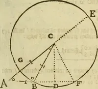
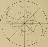
raphically illustrated by meansof valve diagrams, of which there are several differentkinds, notably the Bilgram and Zeuner. The Zeuner dia-^^•am will be made use of in this instance. Valves and Valve Setting 379 Figure 123 shows the total movement of the valve, re-gardless of lap and lead. First… … Fig. 123 6 equals the radius of eccentricity. Line C D representsthe position of the crank when the valve is at mid travel! or in its central position, D being the location of the crankpin. Eeferring back to Fig. 116, the valve is there shownin its central position, and supposed to be moving in…