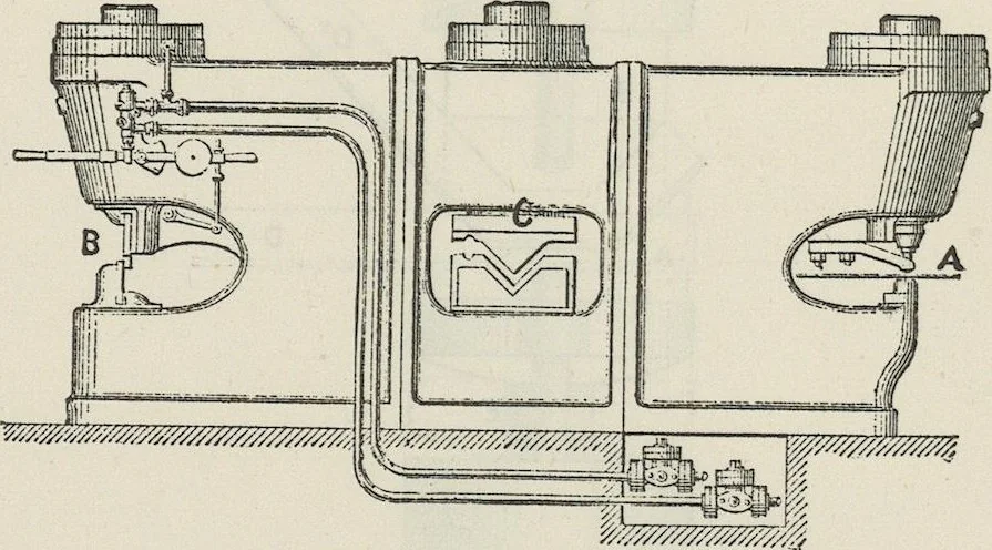
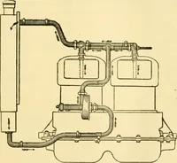
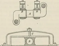
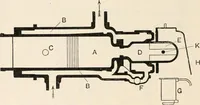
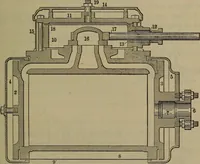
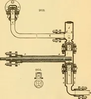
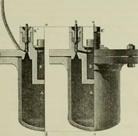
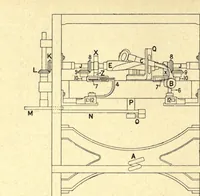
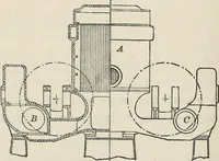
e on this principle , called a “ Hydraulic Joggling Press, ” is shown by fig . 31 . Suitäble dies A and B are fixed in the hydraulic press . The dotted line shows the bottom table in position , when the angle of the T bar D to be bent is placed on the top of the die A . On the ram E rising , the… … Fig . 32 . stepped , so that although the cable is cut by one stroke of the machine , it is not done at the same moment . This enables the cylinder to be rednced to one - half the size that would be required were both sides of the cable to be cut simultaneously ; and as the pressure employed is…
e-rara · Eisenbibliothek Schlatt · No known copyright restrictions. Free to use for anything.