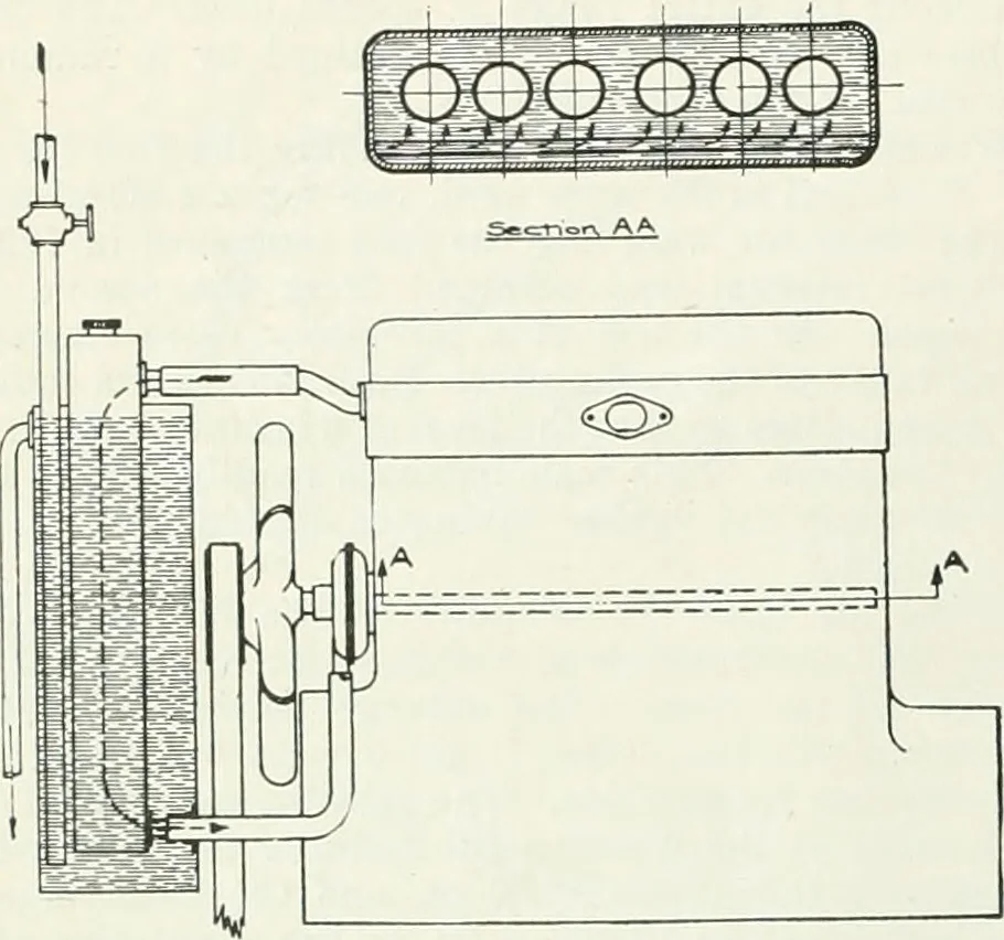
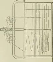
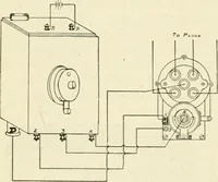
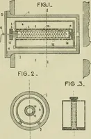
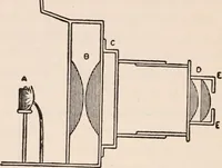
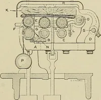
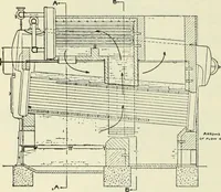
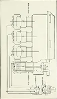
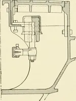
Fig. 12 (below)—Vertical section of 2-iv. carbu-reter used in the tests Fig. M—Parts of engine used in lest. Of thetwo pistons nt top, the our nearer the centergives the 4.25 to 1 compression ratio, while thatat the right (jives a 5 to 1 ratio and is of the con-stant clearance t>j\>e. Another… … Fig. 13—Diagram of cooling water circulating system, showing method of cooling radiator used during block tests Fig. 17 gives the engine characteristic under constant-speed driving conditions with 4.25 to 1 compression ratioand 3.5 to 1 axle gears. It will be seen that the full-loadbrake…
Automobiles · Aeronautics
Internet Archive · University of Toronto Libraries · Public Domain Mark 1.0. Free to use for anything.