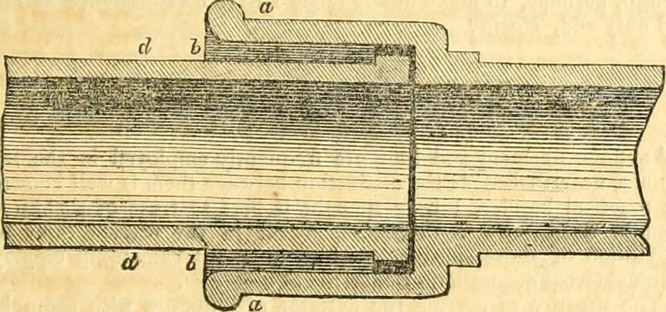
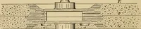
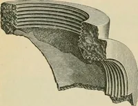
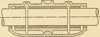
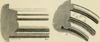
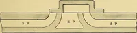
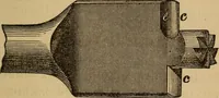
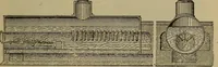
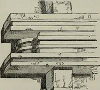
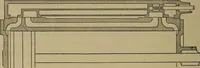
Fig. i- … Reference to the Figures. Figs. 1 and 2, a vertical and side view of a pair of wedges, which is sepa-rati d into two by sawing across in the direction of the transverse line. Fig. 3, a plan of the joint by which two pipes are connected, a a thesocket of one pipe ; d d the spigot-end of the entering…
Civil engineering · Architecture
Internet Archive · Boston Library Consortium · Public Domain Mark 1.0. Free to use for anything.