A course on the stresses in bridge and roof trusses, arched ribs and suspension bridges (1904)
Burr, William H. (William Hubert), 1861-1934 · New York : Wiley · leaf 170
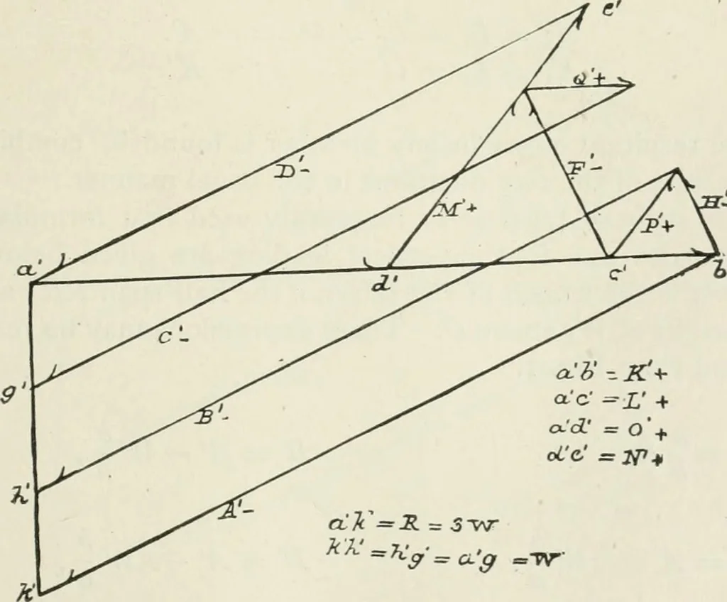
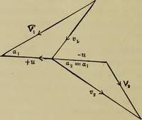
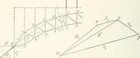
Fig. I. Fig. 2 is the stress diagram for the vertical loading taken,and the notation has precisely the same meaning as before. It is seen from Fig. i, that there is some ambiguity inregard to the stresses C, Q, F, and M. It may be assumed,however, that E = H and P = Q, which makes F = … Fig. 2. The kinds of stresses are shown on the diagrams. I20 NOJV-COA^TIXUOUS T/^USSES IX GENERAL. Fig. 3 is the diagram for the horizontal stresses f and Rollers are supposed to be placed at the foot of A. Henceall horizontal reaction will be found at the foot of A^. Asshown, that reaction will be…
Trusses · Bridges
Internet Archive · California Digital Library · Public Domain Mark 1.0. Free to use for anything.