Elements of graphic dynamics; an elementary textbook for students of mechanics and engineering (1919)
Andrews, Ewart S. (Ewart Sigmund) · London, Chapman and Hall, Ltd. · leaf 121
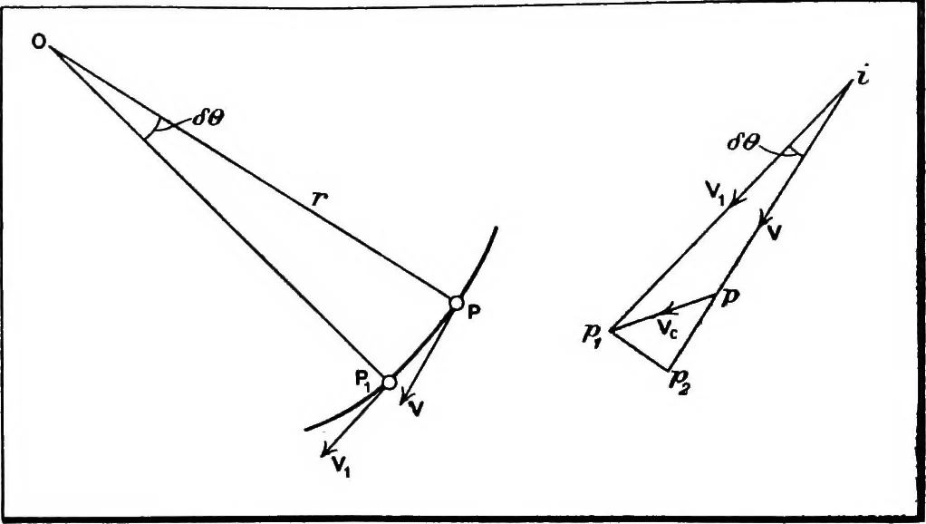
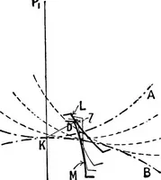
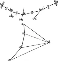
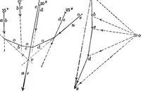
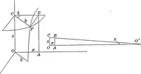
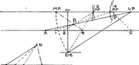
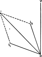
ng and return speeds. In the present case the latter ratio comes about 047. Thediagram of velocity variation shown in Fig. 62 is obtained asfollows: Draw the oscillating slotted lever in any positionPB, and find the corresponding point E on the tool stroke.There are two positions of the crank-pin… … FiG. 63.—Diagram Illustrating Acceleration. responding velocities Ye of cutting and return and plot themup and down respectively upon the stroke base. Repeat thisprocess for a number of points, and join up the points corre-sponding to G and H, thus getting the diagram of velocityvariation as shown.…
Mechanics, Applied · Dynamics · Graphic methods
Internet Archive · Cornell University Library · Public Domain Mark 1.0. Free to use for anything.