International Library of Technology · Scranton, International Textbook Co. · leaf 104
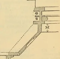
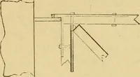
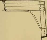
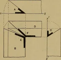
(a) (b) Fig. 1372. manipulate, but the second may form a more rigid con-nection. Fig. 1373 shows how the connections are drawn in for abar-wound armature. The conductor bars are b, b, the end … Fig. 1373.connector is c, and the commutator connection is /; a com-mutator segment is shown at s. The connector is not ac-tually put in as drawn, but one end, in the case of a four-pole machine, is carried around to a conductor situated90 degrees beyond. The shape of this connector is a…
Electrical engineering
Internet Archive · Boston Library Consortium · Public Domain Mark 1.0. Free to use for anything.
![An illustration from [Electric engineering.], 1902, leaf 104](https://img.insideoutlibrary.com/img/1024/ia-electricengineer02inte-104-21.webp)