International Library of Technology · Scranton, International Textbook Co. · leaf 353
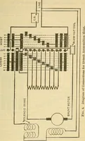
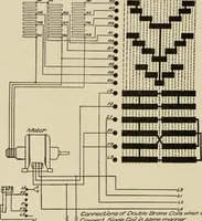
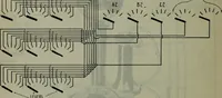
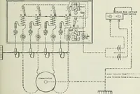
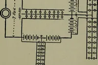
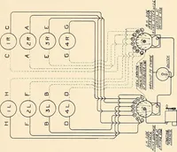
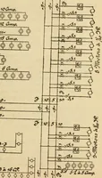
w 6rcii4r?cled en Mefor frame To Tro//ey. Fig. 16. six points, and a development of the drum with the variousconnections is shown in Fig. 16. This diagram shows asingle motor, of which A and F are the armature and field,respectively. It is operated by a single controller. In this £fin t t t i … § 24 ELECTRIC RAILWAYS. 25 controller figure and in those to follow, the drum contactarcs are indicated by black bands, which represent the arcsstraightened or developed out flat. The finger stands onthe poAver drum, and on the reverse drum connection boardsare represented by the row of square…
Electrical engineering
Internet Archive · Boston Library Consortium · Public Domain Mark 1.0. Free to use for anything.
![An illustration from [Electric engineering.], 1902, leaf 353](https://img.insideoutlibrary.com/img/1024/ia-electricengineer04inte-353-152.webp)