International Library of Technology · Scranton, International Textbook Co. · leaf 81
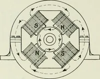
diagram.Fig. 24; i, ^, 3, and 4 represent the field coils of a four-poledynamo, there being a break in coil 2 at B. The terminals aand e of the field winding are connected to the + and — ter-minals of a live circuit; that is, a circuit connected toa dynamo in operation. It will be seen that… … Fig. 24. therefore, a voltmeter connected to a and b^ as. at F, willshow no deflection. But terminal c of coil 2 is connected to the — side of the circuit;so a voltmeter connectedto b and c, as at F,, willshow a deflection, and, infact, will indicate the dif-ference of potential be-tween a and e.…
Electrical engineering
Internet Archive · Boston Library Consortium · Public Domain Mark 1.0. Free to use for anything.
![An illustration from [Electric engineering.], 1902, leaf 81](https://img.insideoutlibrary.com/img/1024/ia-electricengineer04inte-81-22.webp)
![An illustration from [Electric engineering.] (1902)](https://img.insideoutlibrary.com/img/200/ia-electricengineer03inte-309-187.webp)