Mechanical drawing self-taught: comprising instructions in the selection and preparation of drawing instruments. Elementary instruction in practical mechanical drawing. Together with examples in simple geometry and elementary mechanism, including screw threads, gear wheels, mechanical motions, engines and boilers (1889)
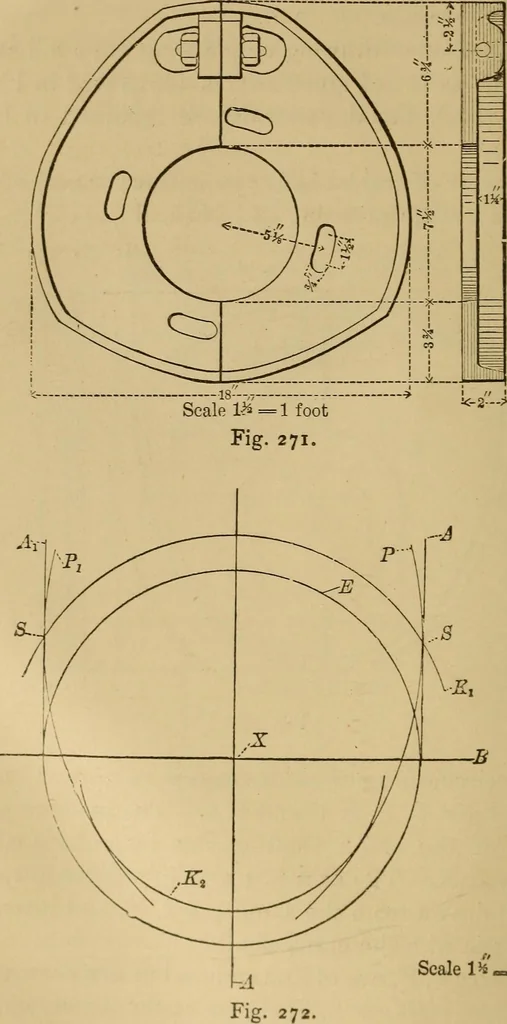
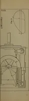
Scale 1^ = ] TojtFig. 270. 2^ The circumference of the cam is composed of fourn\rved lines, P, F, K i, and K 2. The position of thecentre of the crank shaft in this irregularly curvedbody is at X. The arcs K i and K 2 differ in radius,but are drawn from the same point, X, and hence areconcentric… … Scale l^—l foot PLOTTING MECHANICAL MOTIONS. 239 the arcs P, P, with the arc K i. Thus arcs P, P, areeccentric to the crank shaft. To draw the cam place one point of the dividers atX, which is the centre of the crank shaft, and drawthe circle E equal to width of yoke, 18 inches.Through this centre…
Mechanical drawing
Internet Archive · Library of Congress · Public Domain Mark 1.0. Free to use for anything.
![An illustration from [Electric engineering.] (1902)](https://img.insideoutlibrary.com/img/200/ia-electricengineer04inte-420-187.webp)
![An illustration from [Graphophone patents] (1878)](https://img.insideoutlibrary.com/img/200/ia-graphophonepaten15unit-47-43.webp)