Ludy, Llewellyn V., 1875- [from old catalog], American Technical Society · Chicago, American technical society · leaf 111
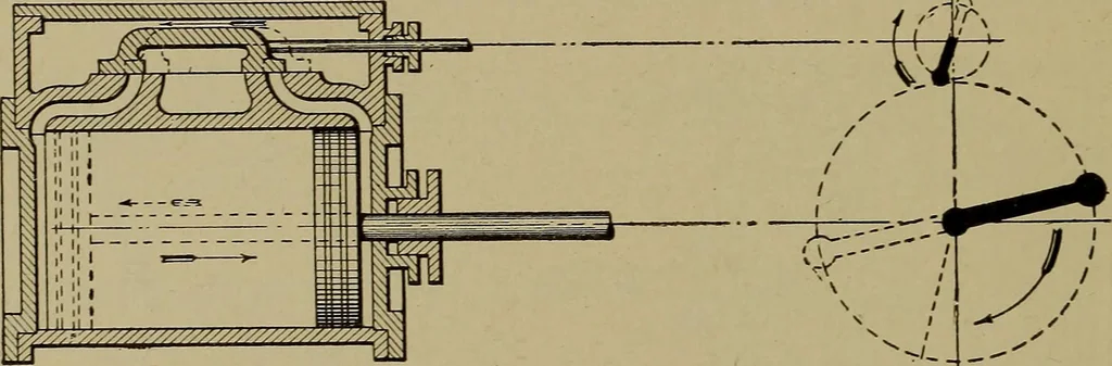
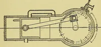
ed position of crank and eccentric in Fig. 10 shows the valvereturned to the point of compression, which continues until the con-ditions of Fig. 6 are again reached and the opening valve allows steamagain to enter the cylinder. 8 VALVE GEARS This process has been traced step by step for one end… … >/ --• Fig. 10. Position of Valve and Cylinder for Head-End Release the crank end. As the inside lap is less than the outside lap, theexhaust continues longer than the admission. Fig. 9 shows the relative positions of crank, eccentric, andvalve when the exhaust closes on the crank end and…
Indicators for steam-engines · Steam-engines
Internet Archive · Library of Congress · Public Domain Mark 1.0. Free to use for anything.