Ludy, Llewellyn V., 1875- [from old catalog], American Technical Society · Chicago, American technical society · leaf 177
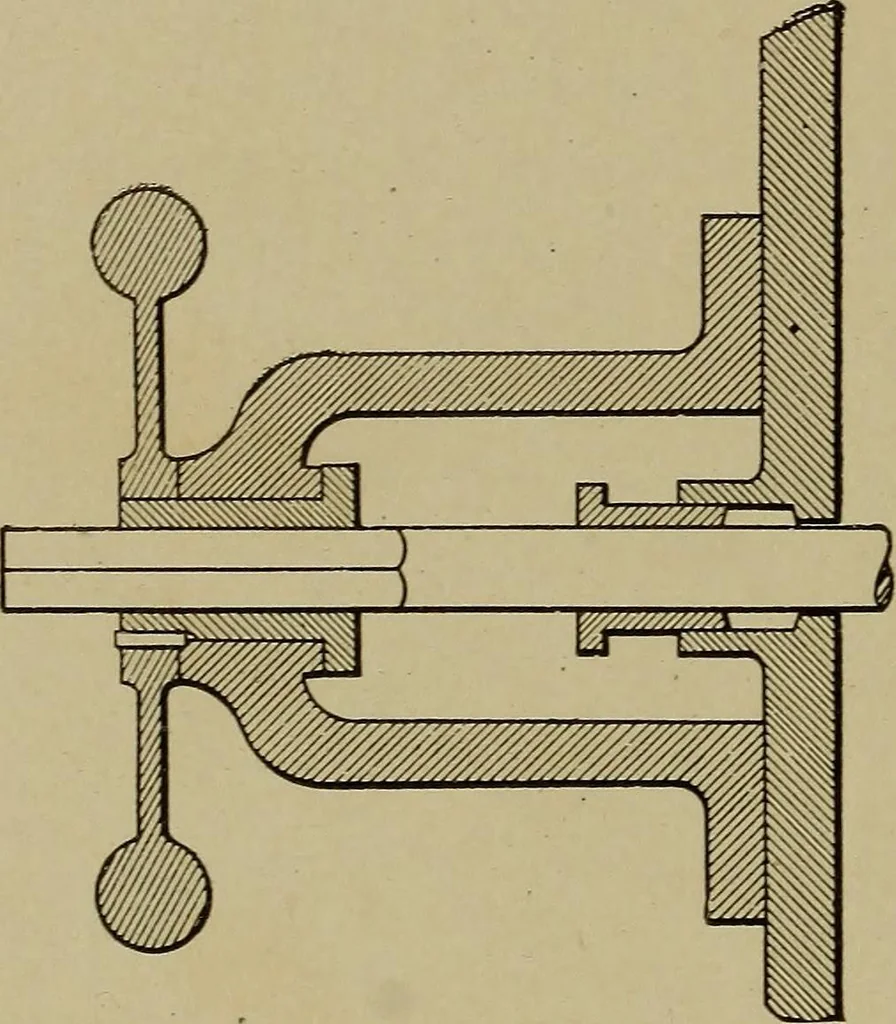
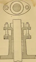
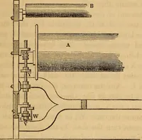
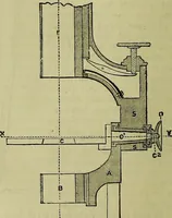
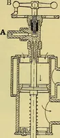
utside lap on the mainvalve be f inch, the lead A inch, the compression 5 per cent of thestroke, and let the ratio of the length of the crank to connecting rodbe 1 to 6. In Fig. 69, draw X 0 Y, the main valve travel, equal to 4 inches.Lay off X D equal to 5 per cent of 4 or 0.2 inches, and with a… … Fig. 68. Stuffing Box and Valve Spindleof Meyer Gear VALVE GEARS 75 similar manner. Lay off 0 I equal to the lap plus the lead, and drawthe valve circle for the main valve through / and 0 with a diameterequal to its. eccentricity of 2 inches. To do this, take a radius equalto 1 inch, and draw arcs…
Indicators for steam-engines · Steam-engines
Internet Archive · Library of Congress · Public Domain Mark 1.0. Free to use for anything.