Steam engines, prepared in the Extension division of the University of Wisconsin (1919)
Shealy, Edward Marvin · New York, McGraw-Hill · leaf 164
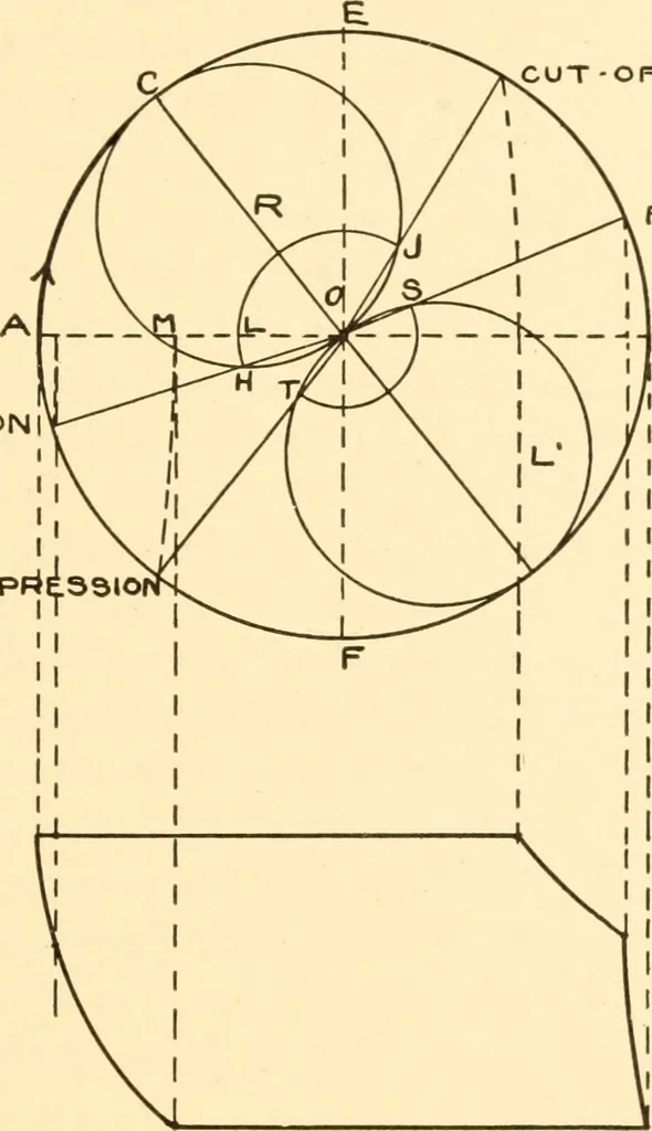
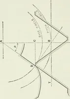
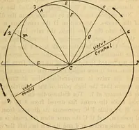
p circle TS must be drawn with aradius equal to the exhaust lap. The four positions of the crank,at admission, cut-off, release, and compression may now bedrawn on the diagram as shown in Fig. 88. Since admission andcut-off, as shown here, take place when the valve is displaced tothe right, and… … RELEASE. -J B Head End Indicator Diagram Fig. 88. of the cylinder, if there is no rocker arm, the direction of rotationbeing clockwise, as indicated by the arrowhead. With the crank positions at admission, cut-off, release, andcompression as shown in Fig. 88 the approximate shape of theindicator…
Steam-engines
Internet Archive · Library of Congress · Public Domain Mark 1.0. Free to use for anything.